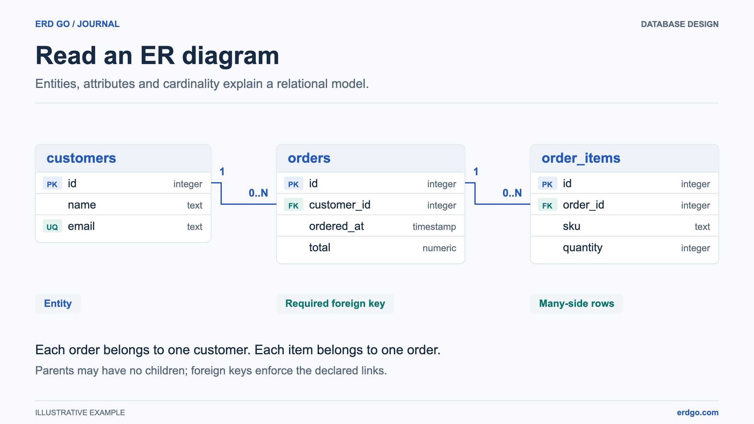
SQL examples use PostgreSQL unless another dialect is named. Short snippets assume their referenced tables already exist. Validate DDL in your target database before applying it.
What is an ERD?
An Entity Relationship Diagram (ERD) is a visual representation of the entities in a database and the relationships between them. First introduced by Peter Chen in 1976, ERDs have become the standard way to model and communicate database structure during the design phase of software development.
Whether you're building a new application from scratch or reverse-engineering an existing database, ERDs help you understand how data is organized, how tables relate to each other, and where potential issues like redundancy or missing relationships might exist.
Core Components of an ERD
Entities
An entity represents a real-world object or concept that can be distinctly identified. During relational design, an entity often maps to a table; multivalued attributes and many-to-many relationships may require additional tables. For example, users, orders, and products are typical entities in an e-commerce system.
Attributes
Attributes describe the properties of an entity. They become the columns of a table. Each attribute has a data type (INTEGER, VARCHAR, TIMESTAMP, etc.) and may have constraints like NOT NULL, UNIQUE, or DEFAULT.
CREATE TABLE users (
  id SERIAL PRIMARY KEY,
  name VARCHAR(100) NOT NULL,
  email TEXT UNIQUE,
  created_at TIMESTAMP DEFAULT now()
);
Relationships
Relationships describe how entities are connected. They're implemented through foreign keys in relational databases. The three main types are:
- One-to-One (1:1) — Each record relates to at most one record on the other side. A user may have an optional profile; mandatory participation needs additional enforcement.
- One-to-Many (1:N) — One record in Table A relates to multiple records in Table B. Example: one customer places many orders.
- Many-to-Many (M:N) — Records in both tables can relate to multiple records in the other. Implemented via a junction table. Example: students enroll in multiple courses, and each course has multiple students.
Types of ERDs
Conceptual ERD
The highest level of abstraction. It shows entities and their relationships without any technical detail. Business stakeholders use conceptual ERDs to understand the domain model.
Logical ERD
Adds more detail including attributes, primary keys, and data types. It's independent of any specific database management system (DBMS).
Physical ERD
The implementation level describes database-specific types, keys, constraints, and indexes. Erd Go visualizes the supported schema details in your SQL DDL; a diagram does not capture every database object or prove that a migration is valid.
Cardinality and Notation
Cardinality defines the numerical relationship between entities. Common notations include:
- Crow's Foot Notation — The most widely used. Uses symbols at the ends of lines: a single line (one), a crow's foot (many), a circle (zero/optional).
- Chen Notation — The original ERD notation using diamonds for relationships and ovals for attributes.
- UML Notation — Uses numbers and asterisks (1, 0..1, 1..*) at line ends.
The SQL-to-ERD editor visualizes relational tables and foreign-key connectors. For conceptual Chen and EER notation, use the ERD Builder. Read the endpoint labels and nullability rather than assuming every diagram uses the same notation.
Creating ERDs from SQL
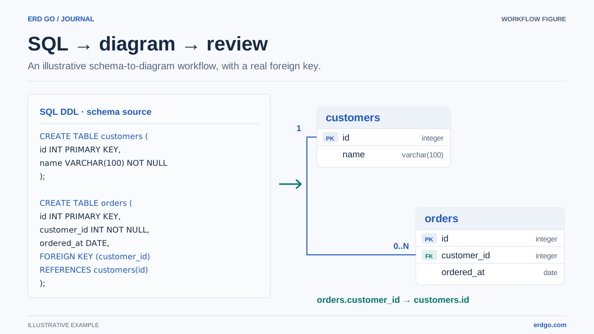
Instead of drawing diagrams manually, you can generate ERDs directly from SQL DDL statements. Here's an example that creates a simple e-commerce schema:
CREATE TABLE customers (
  id SERIAL PRIMARY KEY,
  name VARCHAR(100) NOT NULL,
  email TEXT UNIQUE NOT NULL
);

CREATE TABLE orders (
  id SERIAL PRIMARY KEY,
  customer_id INTEGER REFERENCES customers(id),
  total NUMERIC(10, 2) NOT NULL,
  status VARCHAR(20) DEFAULT 'pending',
  created_at TIMESTAMP DEFAULT now()
);

CREATE TABLE order_items (
  id SERIAL PRIMARY KEY,
  order_id INTEGER REFERENCES orders(id),
  product_name VARCHAR(200) NOT NULL,
  quantity INTEGER CHECK (quantity > 0),
  price NUMERIC(10, 2) NOT NULL
);
Paste this SQL into Erd Go's editor to generate a visual ERD with tables connected by their foreign key relationships.
Best Practices for ERD Design
- Name entities clearly — Use descriptive, plural nouns (e.g.,
users,orders) for tables. - Define primary keys — Every table should have a primary key for unique identification.
- Use foreign keys explicitly — Always define relationships with REFERENCES or ALTER TABLE constraints.
- Normalize your schema — Follow normalization rules (1NF, 2NF, 3NF) to reduce redundancy.
- Keep it readable — Don't overcrowd your ERD. Group related tables together.
- Version your schema — Keep your SQL DDL in version control alongside your code.