SQL examples use PostgreSQL unless another dialect is named. Short snippets assume their referenced tables already exist. Validate DDL in your target database before applying it.
Understanding SQL Relationship Patterns
Relational databases derive their power from the connections between tables. Whether you are designing a small application or an enterprise data warehouse, choosing the correct relationship pattern determines how efficiently you can store, query, and maintain your data. The three fundamental patterns—one-to-one, one-to-many, and many-to-many—cover many common associations; recursive and higher-degree relationships need additional modeling.
In this guide we break down each pattern with PostgreSQL examples, explore the role of junction tables, and show how these relationships appear on an Entity-Relationship Diagram (ERD). If you want to visualize your own schema right now, open the Erd Go editor and paste supported CREATE TABLE definitions to generate a diagram.
One-to-Many Relationships
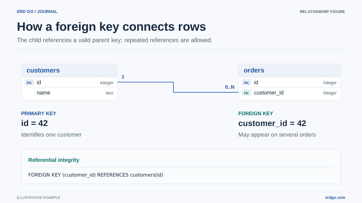
A one-to-many (1:N) relationship is the most common pattern in database design. It means that a single row in the parent table can be referenced by many rows in the child table, and a non-null child foreign key points to one parent. A nullable foreign key permits a child without a parent.
Classic Example: Departments and Employees
A company has many departments, and each department contains multiple employees. However, every employee belongs to exactly one department at any given time.
CREATE TABLE departments (
    id          SERIAL PRIMARY KEY,
    name        VARCHAR(100) NOT NULL,
    location    VARCHAR(255),
    created_at  TIMESTAMP DEFAULT CURRENT_TIMESTAMP
);

CREATE TABLE employees (
    id              SERIAL PRIMARY KEY,
    first_name      VARCHAR(50) NOT NULL,
    last_name       VARCHAR(50) NOT NULL,
    email           VARCHAR(255) UNIQUE NOT NULL,
    department_id   INT NOT NULL,
    hire_date       DATE DEFAULT CURRENT_DATE,
    CONSTRAINT fk_department
        FOREIGN KEY (department_id)
        REFERENCES departments (id)
        ON DELETE RESTRICT
        ON UPDATE CASCADE
);
Key Implementation Details
- The foreign key (
department_id) always lives on the many side—theemployeestable in this case. ON DELETE RESTRICTprevents accidentally removing a department that still has employees assigned.ON UPDATE CASCADEensures that if a department’s primary key changes, all employee rows update automatically.- Adding an index on
department_idcan help joins and department filters; confirm the benefit with representative data and an execution plan.
Querying One-to-Many Data
-- All employees in the Engineering department
SELECT e.first_name, e.last_name, d.name AS department
FROM employees e
JOIN departments d ON d.id = e.department_id
WHERE d.name = 'Engineering';

-- Count employees per department
SELECT d.name, COUNT(e.id) AS headcount
FROM departments d
LEFT JOIN employees e ON e.department_id = d.id
GROUP BY d.id, d.name
ORDER BY headcount DESC;
Other everyday one-to-many examples include authors → blog posts, customers → orders, and categories → products.
Many-to-Many Relationships
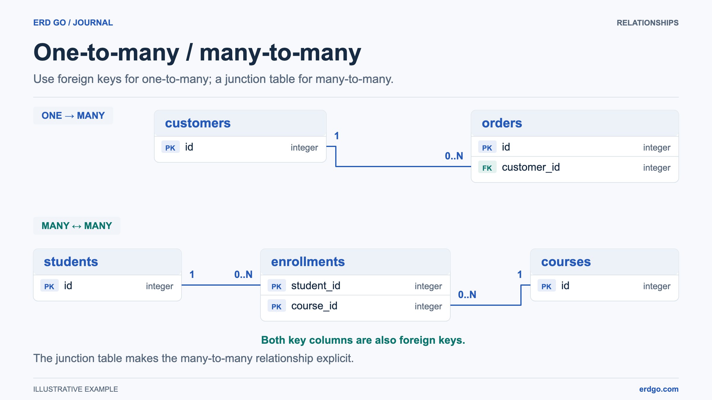
A many-to-many (M:N) relationship exists when rows on both sides can be associated with multiple rows on the other side. Relational databases cannot represent this directly with a single foreign key, so we introduce a junction table (also called a bridge, join, or associative table).
Classic Example: Students and Courses
A student can enroll in many courses, and each course can have many students. The junction table enrollments sits between them and holds the foreign keys to both sides.
CREATE TABLE students (
    id          SERIAL PRIMARY KEY,
    full_name   VARCHAR(120) NOT NULL,
    email       VARCHAR(255) UNIQUE NOT NULL,
    enrolled_on DATE DEFAULT CURRENT_DATE
);

CREATE TABLE courses (
    id          SERIAL PRIMARY KEY,
    title       VARCHAR(200) NOT NULL,
    credits     SMALLINT NOT NULL DEFAULT 3,
    department  VARCHAR(100)
);

CREATE TABLE enrollments (
    student_id  INT NOT NULL REFERENCES students (id) ON DELETE CASCADE,
    course_id   INT NOT NULL REFERENCES courses (id) ON DELETE CASCADE,
    enrolled_at TIMESTAMP DEFAULT CURRENT_TIMESTAMP,
    grade       CHAR(2),
    PRIMARY KEY (student_id, course_id)
);
Why a Junction Table?
- The composite primary key (
student_id, course_id) allows one row per student–course pair. If repeat enrollment across terms is required, include a term in the business key or model each enrollment separately. - You can attach extra attributes to the relationship itself, such as
gradeorenrolled_at, which belong to neither entity alone. ON DELETE CASCADEon both foreign keys means that removing a student or course automatically cleans up the enrollment rows.
Querying Many-to-Many Data
-- All courses for a specific student
SELECT c.title, c.credits, e.grade
FROM enrollments e
JOIN courses c ON c.id = e.course_id
WHERE e.student_id = 42;

-- Students enrolled in 'Database Systems'
SELECT s.full_name, s.email
FROM enrollments e
JOIN students s ON s.id = e.student_id
JOIN courses c ON c.id = e.course_id
WHERE c.title = 'Database Systems';
Real-world many-to-many examples include users ↔ roles, products ↔ tags, actors ↔ movies, and orders ↔ products (via an order_items junction table that also stores quantity and price).
One-to-One Relationships
A one-to-one (1:1) relationship means each row in Table A maps to at most one row in Table B, and vice versa. This pattern is less common but useful for splitting rarely accessed or sensitive columns into a separate table.
CREATE TABLE users (
    id          SERIAL PRIMARY KEY,
    username    VARCHAR(60) UNIQUE NOT NULL,
    email       VARCHAR(255) UNIQUE NOT NULL
);

CREATE TABLE user_profiles (
    user_id     INT PRIMARY KEY REFERENCES users (id) ON DELETE CASCADE,
    bio         TEXT,
    avatar_url  VARCHAR(500),
    birthdate   DATE,
    updated_at  TIMESTAMP DEFAULT CURRENT_TIMESTAMP
);
Notice that user_profiles.user_id is both the primary key and the foreign key. This constraint enforces the one-to-one mapping at the database level—each user can have at most one profile row.
How Relationships Appear in ERDs
An Entity-Relationship Diagram uses lines and symbols between tables to convey cardinality at a glance. The two most popular notations are Crow’s Foot and Chen notation.
| Relationship | Crow’s Foot Symbol | How to Read |
|---|---|---|
| One-to-One | ||—|| | Exactly one on each side |
| One-to-Many | ||—< | One on left, many on right (crow’s foot end) |
| Many-to-Many | >—< | Many on both sides; implemented via junction table |
These text symbols are shorthand for maximum cardinality. Optionality needs an additional zero or one marker; a foreign key alone does not require a parent to have any children.
When you model a many-to-many relationship in an ERD tool, you typically see three boxes—two entity tables and the junction table between them, each connected by a one-to-many line.
Paste any of the SQL examples from this article into the Erd Go editor to see the diagram generated automatically, complete with foreign-key arrows and cardinality indicators.
Choosing the Right Relationship Pattern
Selecting the wrong cardinality leads to data duplication, complex queries, and integrity bugs. Use this decision framework:
- Can one row on side A relate to many rows on side B, but not vice versa? → One-to-Many. Place the foreign key on side B.
- Can rows on both sides relate to many rows on the other? → Many-to-Many. Create a junction table with composite key.
- Is the mapping strictly 1:1 and you need table separation? → One-to-One. Use the same primary key as the foreign key.
When in doubt, sketch your schema first. A quick ERD reveals relationship issues far earlier than running into constraint errors in production. Try building your diagram in the Erd Go editor—it takes seconds and can save hours of debugging.